Product Description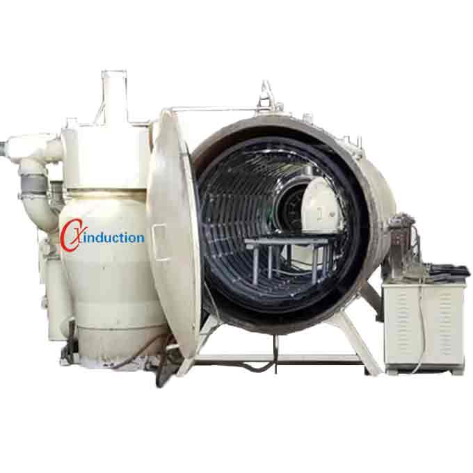
Brazing in a vacuum furnace is a brazing process in which a brazed workpiece is placed in a vacuum furnace, and the workpiece is in a vacuum state during brazing to avoid oxidation of the base metal, and under high temperature vacuum conditions, The surface oxides of the base material is volatilized at high temperatures, and are eliminated by the vacuum equipment system, and the residual brazing filler metal during brazing is also volatilized by vacuum equipment. Brazing in a vacuum furnace, there is no need to add the brazing flux. Vacuum equipment is composed of mechanical vacuum pump, diffusion pump, vacuum connecting pipe and vacuum butterfly valve and so on. It can improve the vacuum degree of the system and can have a positive effect on the brazing quality. Generally, the vacuum degree of brazing in vacuum furnace is within 1.33 * 10-1- 1.33 * 10-3Pa.
Application
It is suitable for brazing the stainless steel and high temperature alloy by using copper and nickel-based brazing filler metal, especially suitable for the high-temperature alloy containing titanium and aluminum; copper, nickel, superalloy and silver-titanium alloy with silver brazing filler metal, and cobalt alloy or a titanium alloy with cobalt-based brazing filler metal, or the like.
Features
The main advantage of brazing in vacuum furnace is that the brazing quality is high, the workpiece is not oxidized, the deformation is small, and it can brazing other materials that cannot be brazed by other brazing method. However, due to the easy evaporation of the metal under vacuum, the brazing should be properly controlled, that is the melting point of the brazing, the melting temperature, the time of infiltration and penetration of the base material. Therefore, it is not advisable to use brazing filler metal with a large content of elements such as zinc, cadmium, manganese, magnesium and phosphorus during brazing, and it is not suitable to use a workpiece containing a large amount of these elements in the base material for brazing in a vacuum furnace.
Technical Data
| Model |
CX-VBF-600 |
| Type |
Horizontal with double doors |
| Power Supply |
3/N/PE AC/380V 50Hz (customized according to your power gird) |
| Max. Output Power |
90 KW (heating 60KW, pump 20KW, others 10KW) |
| Max. Temperature |
1300°C |
| Max. Continuous Working Temperature |
≤1250°C |
| Temperature Uniformity |
±5°C (Empty, Room Temperature Furnace) |
| Max Heating Rate |
≤60 min from Room Temperature to 1200°C,Empty Furnace |
| Ultimate Vacuum |
10-4 pa |
| Vacuum Chamber Pressure Rise Rate |
0.4 Pa/h (Empty, Room Temperature Furnace) |
| Cooling Method |
Natural Cooling |
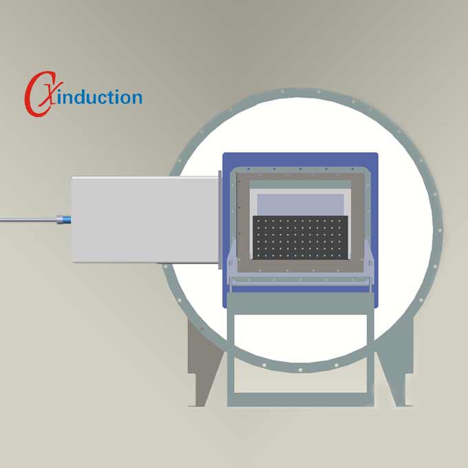
Furnace Structure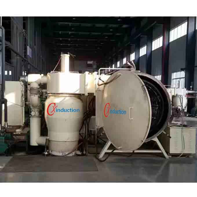
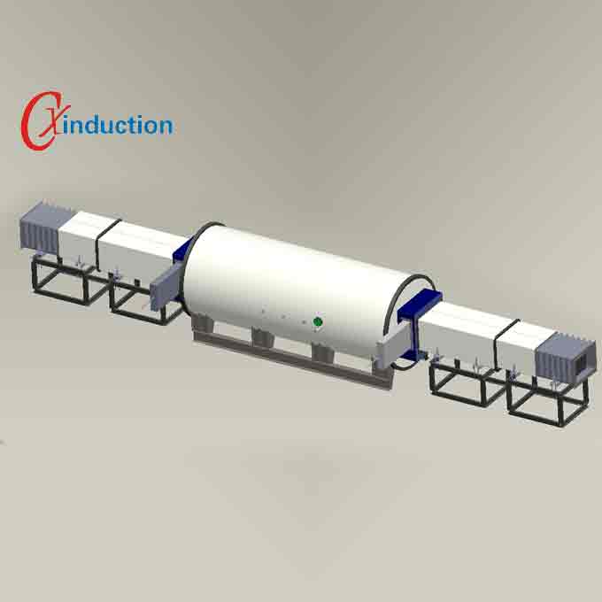
Vacuum Brazing furnace, model CX-VBF-600 consists of Furnace Body, Heating Chamber, Vacuum System, Gas Charging System, Water Cooling System, Electronic Control and Power Supply System.
1. Furnace Body: consists of furnace shell, furnace door, locking mechanism, furnace support etc. Both the furnace shell and door are double-wall which are made of SUS 304 and have integral water cooling passages. The furnace door is made from double elliptical head and a circular flange by welding, and there is a O-sealing ring on the flange. The front door is a common work door. The workpiece is loaded and unloaded from the front door. There is a heating chamber, electrode and exhaust port of the main vacuum pump on the furnace body.
2.Heating Chamber: It is a cylindrical chamber and consists of heating element, heat shield and material table. The heating element is high strength molybdenum wire and insulated by special designed ceramic parts to avoid the shirt circuit caused by welding volatilization. The heating zone can be disassembled separately and it is easy to replace when damaged. The heating power source is connected to heating element through soft copper wire, copper bar, copper electrode. The circuit and furnace body have good insulation performance which is easy to clean, disassemble and replace.
3.Vacuum system: includes a mechanical pump and a diffusion pump. There are vacuum gauge sockets on each valve and pipe. And the vacuum measuring devices are equipped for each pipeline section to facilitate vacuum measurement in each pipeline.
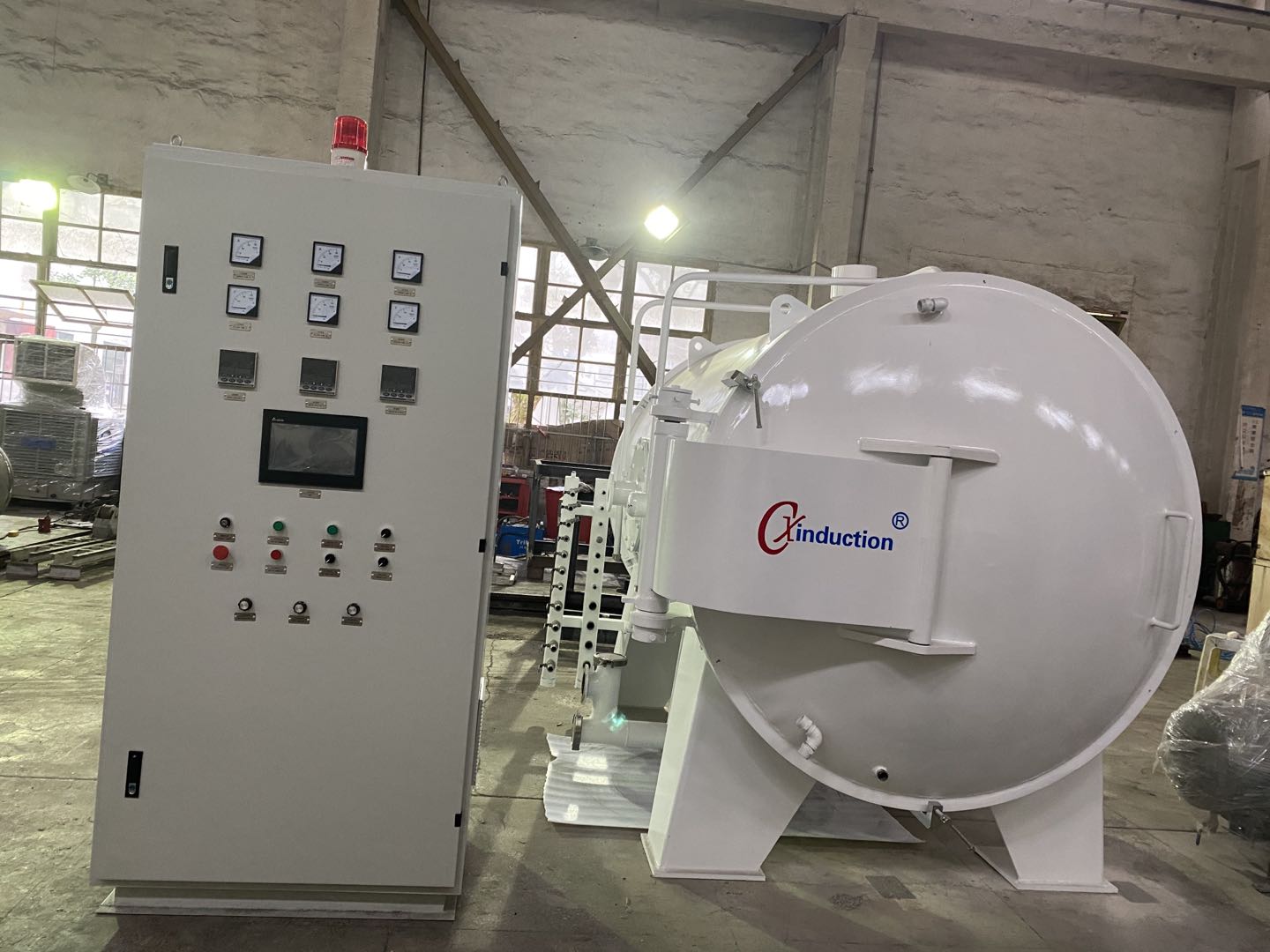
4.Electronic Controlling System:
4.1 It includes Touch Screen, PLC, Thyristor Voltage Regulator, Vacuum Gauge to achieve the function of power supplying, controlling, recording, monitoring, alarming and protecting.
4.2 It achieved high temperature control accuracy by using Germany Siemens PLC and Japanese Shimaden Temperature Controller. Meanwhile, the PLC roundly control the operation of the furnace. According to the process requirements, the sequence control signals are provided, and the feedback signals at the scene are collected to provide conversion, interlocking, indication and alarm signals. In addition to loading and unloading, the entire process can be automated and equipped with a manual operating system.
4.3 There two pieces of thermocouple to measure the temperature in the furnace and learn the temperature uniformity at any time.
4.4 The furnace controlling interface is touch screen controlling system. Through the communication with the PLC, the temperature and vacuum curves can be set up and recorded to develop and query the process. The furnace’s running status can be displayed in real time.
4.5 It has over-temperature and water-breaking safety protection function, and has sound and light alarm system. The furnace body is equipped with safety valve device, and there are interlocking circuits such as air pressure, vacuum degree, water pressure and heating.
4.6 The heating power supply uses a single-phase thyristor power supply, and is powered by a low voltage and a large current. Heating power 60KVA.
4.7 There is a fan cooling system in the control cabinet.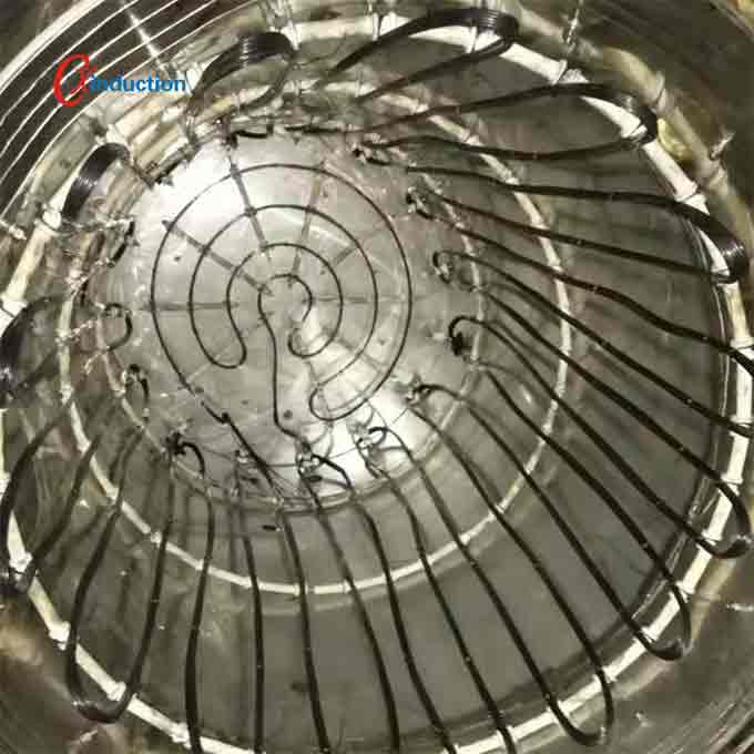
5.Water cooling system: the furnace body, furnace door, vacuum unit, water-cooled electrode, heat exchange system of furnace require cooling water. The cooling water is distributed by a manifold to each cooling part, and it is a closed water circulation system. Each cooling pipe is equipped with a water flow observer and is equipped with a water pressure alarm system. There is a branch which is connected to the tap water pipe for emergency use in case of power failure. Both the inlet and outlet pipes are made of stainless steel pipes.
6.Pneumatic system: consists of pneumatic three-piece (water eliminator, pressure gauge, oil mister), electromagnetic reversing valve and pipeline. Provides clean compressed air to pneumatic actuators such as cylinders, inflation valves, vacuum valves, and more.
7.Inflating and partial pressure system: It consists of large-diameter pneumatic shut-off valve, manual stop valve, trimmer valve, and gas collecting pipe. There is a safety bleed valve when the furnace is deflated. And there is a pressure sensor to control the inflation pressure.
8.Workpiece conveying system: material is loaded by pallet or placed on bearing platform.
9. Safety system: The safety system includes water stop, over temperature, heating over flow, fault self-diagnosis, automatic protection, and prevention of misoperation. And with sound and light alarm prompts and with corresponding interlocking, interlock protection.